


舌侧矫治器关闭间隙上前牙牙周膜应力变化的三维有限元分析
[柳大为1 , 李晶1 , 郭亮2 , 荣起国2 , 周彦恒1, △  ]
]
]
|
|


目的 利用已有的舌侧矫治三维有限元模型并进行加力运算,分析个体化舌侧矫治滑动法关闭上颌拔牙间隙阶段,在颊、腭侧不同力值、不同加力组合方式加力时,上前牙的牙周膜应力分布规律,指导临床应用。方法 建立舌侧矫治三维有限元模型,在ANSYS 11.0软件中分别模拟:(1)上颌第二磨牙作为支抗牙进行单独颊侧加力(力值0.75 N、1.00 N、1.50 N);(2)单独腭侧加力(力值0.75 N、1.00 N、1.50 N);(3)颊、腭侧同时加力(颊侧加力1.00 N+腭侧加力0.50 N、颊侧加力0.75 N+腭侧加力 0.75 N、颊侧加力0.50 N+腭侧加力1.00 N),分析3种加力方式下上前牙牙周膜的最大主应力、最小主应力和von Mises应力的峰值及分布。结果 (1)单纯颊侧加力时(0.75 N、1.00 N、1.50 N)最大主应力:初始,在侧切牙牙周膜唇侧颈部及尖牙牙周膜腭侧及远中颈部均受压应力,随着加力增大,压应力值及牙周膜受压应力范围增大。最小主应力:初始,在侧切牙牙周膜腭侧颈部及尖牙近中颈部受拉应力,随着加力增大,拉应力值及牙周膜受拉应力范围增大,在中切牙的近、远中颈部牙周膜也出现拉应力区。von Mises应力:初始,牙周膜受应力区集中体现的部位为侧切牙唇、腭侧颈部及尖牙远中颈部,随着加力增大,应力值及牙周膜受力范围向根方扩大,最终,尖牙近中颈部牙周膜也出现应力集中区。(2)单纯腭侧加力(0.75 N、1.00 N、1.50 N)最大主应力:初始,尖牙牙周膜远中偏腭侧颈部,及侧切牙远中偏颊侧和腭侧颈部的牙周膜受压应力,随着加力增大,压应力值及牙周膜受压应力范围增大。最小主应力:初始,侧切牙远中邻面颈部及尖牙近中邻面颈部受拉应力,随着加力增大,拉应力值及牙周膜受拉应力范围增大。von Mises应力:初始,牙周膜受应力区集中于尖牙腭侧及近远中邻面偏腭侧的颈部,随着加力增大,应力值及牙周膜受力范围增大,最终在尖牙牙周膜颈部腭侧远中处出现了应力集中区。(3)颊腭侧同时加力时:最大主应力:压应力一直应力集中于尖牙远中偏腭侧颈部牙周膜。最小主应力:拉应力的应力集中区在颊侧加力大于腭侧加力时为侧切牙腭侧颈部牙周膜,随腭侧加力的增大,拉应力应力集中区转移到尖牙牙周膜的近中颈部。von Mises应力:颊腭侧同时加力,牙周膜所受的综合应力较单纯颊(腭)侧加力小。结论 单纯颊侧加力关闭拔牙间隙时,侧切牙及尖牙牙周膜为主要应力集中区,应力大小和范围随施力增大而增大;单纯腭侧加力关闭拔牙间隙时,尖牙牙周膜为主要应力集中区,当力值增大过程中,应力大小和范围增大;采用颊、腭侧不同加力方式组合,压应力的应力集中点均在尖牙远中牙周膜区域,拉应力的应力集中区颊侧加力大于腭侧加力时出现在侧切牙腭侧颈部,随腭侧加力力值增大转移到尖牙近中;综合应力分布情况下颊侧加力1.00 N+腭侧加力0.50 N时,牙周膜应力分布更为均匀,同时应力水平最小。
Objective: To analyze the stress distribution in the periodontal ligament (PDL) under different loading conditions at the stage of space closure by 3D finite element model of customized lingual appliances.Methods: The 3D finite element model was used in ANSYS 11.0 to analyze the stress distribution in the PDL under the following loading conditions: (1) buccal sliding mechanics (0.75 N,1.00 N,1.50 N), (2) palatal sliding mechanics (0.75 N,1.00 N,1.50 N), (3) palatal-buccal combined sliding mechanics (buccal 1.00 N + palatal 0.50 N, buccal 0.75 N + palatal 0.75 N, buccal 0.50 N+ palatal 1.00 N). The maximum principal stress, minimum principal stress and von Mises stress were evaluated.Results: (1) buccal sliding mechanics(0.75 N,1.00 N,1.50 N): maximum principal stress: at the initial of loading, maximum principal stress, which was the compressed stress, distributed in labial PDL of cervix of lateral incisor, and palatal distal PDL of cervix of canine. With increasing loa-ding, the magnitude and range of the stress was increased. Minimum principal stress: at the initial of loading, minimum principal stress which was tonsil stress, distributed in palatal PDL of cervix of lateral incisor and mesial PDL of cervix of canine. With increasing loading, the magnitude and range of minimum principal stress was increased. The area of minimum principal stress appeared in distal and mesial PDL of cervix of central incisor. von Mises stress:it distributed in labial and palatal PDL of cervix of la-teral incisor and distal PDL of cervix of canine initially. With increasing loading, the magnitude and range of stress was increased towards the direction of root. Finally, there was stress concentration area at mesial PDL of cervix of canine. (2) palatal sliding mechanics(0.75 N,1.00 N,1.50 N): maximum principal stress: at the initial of loading, maximum principal stress which was the compressed stress, distributed in palatal and distal PDL of cervix of canine, and distal-buccal and palatal PDL of cervix of late-ral incisor. With increasing loading, the magnitude and range of the stress was increased. Minimum principal stress: at the initial of loading, minimum principal stress which was tonsil stress, distributed in distal-interproximal PDL of cervix of lateral incisor and mesial-interproximal PDL of cervix of canine. With increasing loading, the magnitude and range of the stress was increased.von Mises stress: von Mises stress distributed in palatal and interproximal PDL of cervix of canine. With increasing loading, the magnitude and range of stress was increased. Finally, von Mises stress distributing area appeared at distal-palatal PDL of cervix of canine. (3) palatal-buccal combined sliding mechanics: maximum principal stress: maximum principal stress still distributed in distal-palatal PDL of cervix of canine. Minimum principal stress: minimum principal stress distributed in palatal PDL of cervix of lateral incisor when buccal force was more than palatal force. As palatal force increased, the stress concentrating area transferred to mesial PDL of cervix of canine.von Mises stress: it was lower and more well-distributed in palatal-buccal combined sliding mechanics than palatal or buccal sliding mechanics.Conclusion: Using buccal sliding mechanics,stress majorly distributed in PDL of lateral incisor and canine, and magnitude and range of stress increased with the increase of loading; Using palatal sliding mechanics,stress majorly distributed in PDL of canine, and magnitude and range of stress increased with the increase of loading; With palatal-buccal combined sliding mechanics, the maximum principal stress distributed in the distal PDL of canine. Minimum principal stress distributed in palatal PDL of cervix of lateral incisor when buccal force was more than palatal force. As palatal force was increasing, the minimum principal stress distributing area shifted to mesial PDL of cervix of canine. When using 1.00 N buccal force and 0.50 N palatal force, the von Mises stress distributed uniformly in PDL and minimal stress appeared.
作为隐形矫治的主要方法, 舌侧矫治器托槽粘接于牙齿舌侧面, 达到了完全隐蔽的效果, 受到诸多患者的青睐。2001年德国Wiechmann[1]医师开发出Incognito舌侧矫治系统, 将计算机辅助设计/制造技术应用在舌侧矫治领域, 进行个体化矫治器设计、机械制作, 机械手弯制弓丝。矫治器制作精确, 方便临床操作, 患者感觉更舒适, 使舌侧矫治器为越来越多的正畸医生所接受。
正畸治疗中矫治力作用于牙齿, 通过牙周膜传导至牙周组织, 并引起牙槽骨改建, 这一过程是正畸牙齿移动的生物学基础, 因此, 研究正畸力与牙周膜的作用关系, 对于研究矫治器的生物力学机制及生物力学效应至关重要。以往有一些关于唇侧固定矫治治疗过程中牙周膜应力分布的研究。研究内容尤其是以唇侧矫治过程中, 单颗牙齿受力时牙周膜应力分布的三维有限元分析较多, 如分析单颗尖牙、单颗磨牙移动[2, 3, 4], 中切牙水平受力、压入、伸长、旋转移动[5, 6, 7, 8]等等。与唇侧矫治相比, 舌侧矫治托槽粘接更接近牙齿抗力中心, 有其特殊生物力学特点, 舌侧矫治的加力方式和其生物力学机制均有很大不同, 特别是在舌侧矫治拔牙病例过程中的生物力学机制。在目前的研究中, 对于舌侧矫治牙周膜应力分布的研究多集中在对个别牙齿的研究[9], 而对舌侧矫治关闭间隙过程中, 上前牙整体分析的研究极少。
本研究利用已有三维有限元模型[10, 11], 建立含有牙、牙周膜、上颌牙槽骨、矫治系统的整体三维有限元模型, 通过在三维有限元模型上的加力运算, 分析颊、腭侧不同力值、不同加力组合方式加力时上颌前牙区的牙周膜应力分布规律, 从牙周膜生物力学角度, 探讨符合生物力学原则的加力方式, 为探索最适临床治疗策略提供参考。
根据以往研究[10, 11], 建立一个舌侧矫治器滑动法关闭间隙时的三维有限元模型, 模拟拔除上颌双侧第一前磨牙并关闭拔牙间隙的情况。这个三维有限元模型共分成38个实体模型:牙、牙周膜和托槽各12个, 上颌骨、弓丝各1个。根据患者牙齿的舌侧面形态设计个体化的舌侧托槽底板, 并完全根据临床实际情况设定托槽位置。
参照以往研究[10, 11, 12, 13], 本研究建立的牙周膜模型为各向同性、均质连续的线弹性体材料, 并根据以往研究进行牙周膜弹性模量赋值[10, 14, 15], 牙周膜弹性模量50.0 MPa, 泊松比0.49。同时牙周膜的模型是根据牙根形态进行计算得出, 而非真正的解剖意义上的牙周膜, 并假设牙周膜加力后厚度无变化[16]。在牙根部利用Geomagic软件生成一个0.25 mm的薄壁, 形成牙周膜的三维曲面模型, 分析上颌中切牙、侧切牙及尖牙牙周膜应力分布, 共6个牙周膜模型。使用软件模拟舌侧矫治关闭上颌拔牙间隙时的上前牙三维移动趋势, 观察上颌中切牙、侧切牙及尖牙的牙周膜应力分布[11]。
1.2.1 模拟单纯颊侧加力 根据以往研究[11], 舌侧矫治中, 如采用颊侧加力, 使用弹力链绕过尖牙, 悬吊于尖牙和侧切牙间的弓丝上(图1、2), 因此在三维有限元模型上对于临床情况包含了水平颊向对弓丝的拉力, 尖牙近中邻面所受水平腭向的拉力, 尖牙颊面向远中的拉力及第二磨牙颊面向近中的拉力。由于尖牙颊面到第二磨牙颊面距离过长, 临床中弹力链一般会贴紧第二前磨牙牙面, 故在此处即受到来自尖牙和第二磨牙两个大小相等方向相反的牵引力, 又受到一个对第二前磨牙向腭侧的压力。选择节点如下:弓丝上点(n=365 070, 365 069 ), 尖牙近中邻面受力点(n=327 469, 335 655), 尖牙颊面受力点(n=327 327, 334 900), 第二前磨牙颊面受力点(n=136 607, 130 323), 第二磨牙颊面中点(n=181 256, 204 824), 分别加载力值f0=0.75 N, 1.00 N, 1.50 N。
1.2.2 模拟单纯腭侧加力(每侧0.75 N, 1.00 N, 1.50 N) 根据以往研究[11], 选择位于一侧尖牙托槽上中央的节点(n=376 070)及同侧第二磨牙托槽上中央的节点(n=371 692), 选择对侧相应位置上相同节点(n=373 692, 376 663, 图1、2), 模拟临床单纯腭侧加力情况, 设置两点间力值大小相等、方向相反, 加载力值大小分别为f0=0.75 N, 1.00 N, 1.50 N。
1.2.3 模拟颊腭侧同时加力, 使用如下3组加力模式对模型进行加载 颊侧加力1.00 N+腭侧加力0.50 N, 颊侧加力0.75 N+腭侧加力0.75 N, 颊侧加力0.50 N+腭侧加力1.00 N。
1.2.4 加载及运算 运用ANSYS11.0软件, 观察在牙周膜中的最大主应力、最小主应力及von Mises应力分布变化。
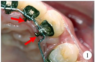 | 图1 颊、腭侧加力拉尖牙的不同施力点Figure 1 Different point where applied buccal or palatal force when retracted canine |
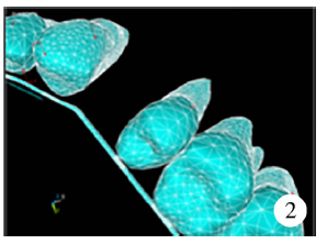 | 图2 单纯颊侧加力三维有限元模型中模拟临床情况的加力Figure 2 Simulated applying buccal force in 3-dimensional finite element model |
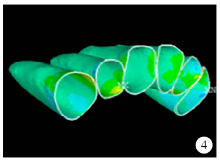
最大主应力(0.75 N、1.00 N、1.50 N):初始, 在侧切牙牙周膜唇侧颈部及尖牙牙周膜腭侧及远中颈部最大主应力均为负值, 表明此处的牙周膜受压应力处于压缩状态(图3)。随着加力增大, 压应力值及牙周膜受压应力范围增大(图4), 最终在侧切牙唇侧颈部偏远中区及尖牙远中面颈部近唇侧区出现了高压应力集中区(图5)。
 | 图3 颊侧加力0.75 N关闭拔牙间隙时牙周膜最大主应力分布图Figure 3 The maximum principal stress distribution when applied 0.75 N buccal force in space closure stage |
 | 图4 颊侧加力1.00 N关闭拔牙间隙时牙周膜最大主应力分布图Figure 4 The maximum principal stress distribution when applied 1.00 N buccal force in space closure stage |
 | 图5 颊侧加力1.50 N关闭拔牙间隙时牙周膜最大主应力分布图Figure 5 The maximum principal stress distribution when applied 1.50 N buccal force in space closure stage |
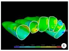
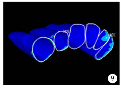
最小主应力(0.75 N、1.00 N、1.50 N):初始, 在侧切牙牙周膜腭侧颈部及尖牙近中颈部牙周膜最小主应力为正值, 表明此处牙周膜所受拉应力处于牵张状态(图6)。随着加力增大, 拉应力值及牙周膜受拉应力范围增大(图7), 最终在侧切牙腭侧颈部及尖牙近中颈部牙周膜出现应力集中点。并在中切牙的近、远中颈部牙周膜均出现拉应力区(图8)。
 | 图6 颊侧加力0.75 N关闭拔牙间隙时牙周膜最小主应力分布图Figure 6 The minimum principal stress distribution when applied 0.75 N buccal force in space closure stage |
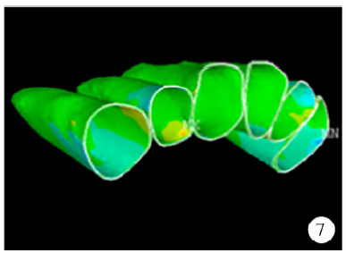 | 图7 颊侧加力1.00 N关闭拔牙间隙时牙周膜最小主应力分布图Figure 7 The minimum principal stress distribution when applied 1.00 N buccal force in space closure stage |
 | 图8 颊侧加力1.50 N关闭拔牙间隙时牙周膜最小主应力分布图Figure 8 The minimum principal stress distribution when applied 1.50 N buccal force in space closure stage |
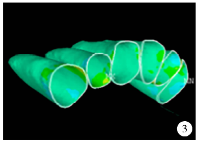
von Mises应力(0.75 N、1.00 N、1.50 N):初始, 牙周膜受应力区集中体现的部位为侧切牙唇、腭侧颈部及尖牙远中颈部(图9)。随着加力增大, 应力值及牙周膜受力范围向根方扩大(图10)。最终, 尖牙近中颈部牙周膜也出现应力集中区(图11)。
 | 图9 颊侧加力0.75 N关闭拔牙间隙时牙周膜von Mises应力分布图Figure 9 The von Mises stress distribution when applied 0.75 N buccal force in space closure stage |
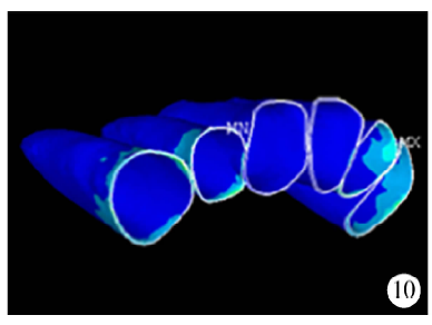 | 图10 颊侧加力1.00 N关闭拔牙间隙时牙周膜von Mises应力分布图Figure 10 The von Mises stress distribution when applied 1.00 N buccal force in space closure stage |
 | 图11 颊侧加力1.50 N关闭拔牙间隙时牙周膜von Mises应力分布图Figure 11 The von Mises stress distribution when applied 1.50 N buccal force in space closure stage |
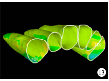
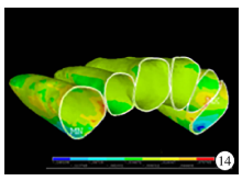
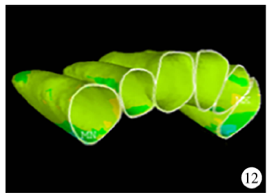
最大主应力(0.75 N、1.00 N、1.50 N):尖牙牙周膜远中偏腭侧颈部最大主应力为负值, 表明此处的牙周膜受压应力处于压缩状态, 侧切牙远中偏颊侧和腭侧颈部的牙周膜也处于压缩状态(图12), 随着加力增大, 压应力值及牙周膜受压应力范围增大(图13), 当加力至1.50 N, 尖牙牙周膜远中偏腭侧颈部受压缩程度最大, 侧切牙远中偏颊侧和腭侧颈部区域压应力较大(图14)。
 | 图12 腭侧加力0.75 N关闭拔牙间隙时牙周膜最大主应力分布图Figure 12 The maximum principal stress distribution when applied 0.75 N palatal force in space closure stage |
 | 图13 腭侧加力1.00 N关闭拔牙间隙时牙周膜最大主应力分布图Figure 13 The maximum principal stress distribution when applied 1.00 N palatal force in space closure stage |
 | 图14 腭侧加力1.50 N关闭拔牙间隙时牙周膜最大主应力分布图Figure 14 The maximum principal stress distribution when applied 1.50 N palatal force in space closure stage |
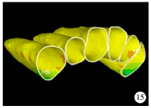
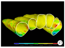
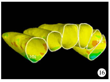
最小主应力(0.75 N、1.00 N、1.50 N):初始, 在侧切牙远中邻面颈部及尖牙近中邻面颈部牙周膜最小主应力为正值, 表明此处牙周膜所受拉应力处于拉伸状态(图15), 随着加力增大, 拉应力值及牙周膜受拉应力范围增大(图16、17)。
 | 图15 腭侧加力0.75 N关闭拔牙间隙时牙周膜最小主应力分布图Figure 15 The minimum principal stress distribution when applied 0.75 N palatal force in space closure stage |
 | 图16 腭侧加力1.00 N关闭拔牙间隙时牙周膜最小主应力分布图Figure 16 The minimum principal stress distribution when applied 1.00 N palatal force in space closure stage |
 | 图17 腭侧加力1.50 N关闭拔牙间隙时牙周膜最小主应力分布图Figure 17 The minimum principal stress distribution when applied 1.50 N palatal force in space closure stage |
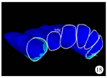
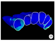
von Mises应力(0.75 N、1.00 N、1.50 N):初始, 牙周膜受应力区集中体现的部位为尖牙腭侧及近远中邻面偏腭侧的颈部(图18), 随着加力增大, 应力值及牙周膜受力范围增大(图19), 最终在尖牙牙周膜颈部腭侧远中处出现了应力集中区(图20)。
 | 图18 腭侧加力0.75 N关闭拔牙间隙时牙周膜von Mises应力分布图Figure 18 The von Mises stress distribution when applied 0.75 N palatal force in space closure stage |
 | 图19 腭侧加力1.00 N关闭拔牙间隙时牙周膜von Mises应力分布图Figure 19 The von Mises stress distribution when applied 1.00 N palatal force in space closure stage |
 | 图20 腭侧加力1.50 N关闭拔牙间隙时牙周膜von Mises应力分布图Figure 20 The von Mises stress distribution when applied 1.50 N palatal force in space closure stage |
通过对颊、腭侧不同加力方式情况下对牙周膜应力情况的观察, 可以从生物学角度对加力方式进行评价, 判断牙周膜在何种加力方式下应力分布更为合理。加力顺序及组合为:颊侧加力1.00 N+腭侧加力0.50 N、颊侧加力0.75 N+腭侧加力 0.75 N、颊侧加力0.50 N+腭侧加力1.00 N。
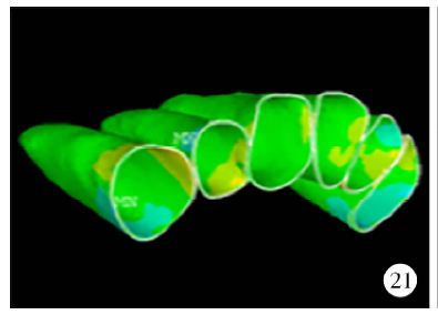
最大主应力:压应力的应力集中区一直集中在尖牙远中偏腭侧颈部牙周膜(图21、22、23)。
 | 图21 颊侧加力1.00 N+腭侧加力0.50 N关闭拔牙间隙时牙周膜最大主应力分布图Figure 21 The maximum principal stress distribution when applied 1.00 N buccal force +0.50 N palatal force in space closure stage |
 | 图22 颊侧加力0.75 N+腭侧加力0.75 N关闭拔牙间隙时牙周膜最大主应力分布图Figure 22 The maximum principal stress distribution when applied 0.75 N buccal force +0.75 N palatal force in space closure stage |
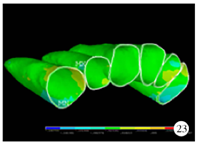 | 图23 颊侧加力0.50 N+腭侧加力1.00 N关闭拔牙间隙时牙周膜最大主应力分布图Figure 23 The maximum principal stress distribution when applied 0.50 N buccal force +1.00 N palatal force in space closure stage |
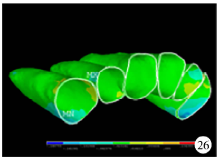
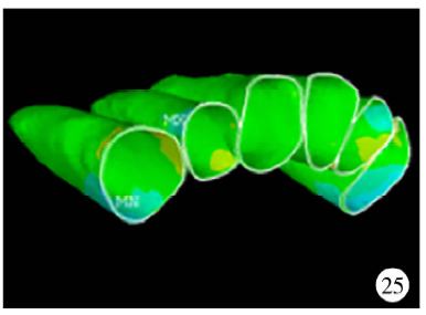
最小主应力:拉应力的应力集中区在颊侧加力大于腭侧加力时为侧切牙腭侧颈部牙周膜, 随腭侧加力的增大, 拉应力应力集中区转移到尖牙牙周膜的近中颈部(图24、25、26)。
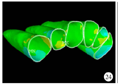 | 图24 颊侧加力1.00 N+腭侧加力0.50 N关闭拔牙间隙时牙周膜最小主应力分布图Figure 24 The minimum principal stress distribution when applied 1.00 N buccal force +0.50 N palatal force in space closure stage |
 | 图25 颊侧加力0.75 N+腭侧加力0.75 N关闭拔牙间隙时牙周膜最小主应力分布图Figure 25 The minimum principal stress distribution when applied 0.75 N buccal force +0.75 N palatal force in space closure stage |
 | 图26 颊侧加力0.50 N+腭侧加力1.00 N关闭拔牙间隙时牙周膜最小主应力分布图Figure 26 The minimum principal stress distribution when applied 0.50 N buccal force +1.00 N palatal force in space closure stage |
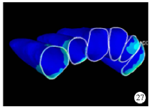
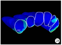
von Mises应力:可见颊腭侧同时加力, 牙周膜所受的综合应力较单纯颊(腭)侧加力小(图27、28、29)。
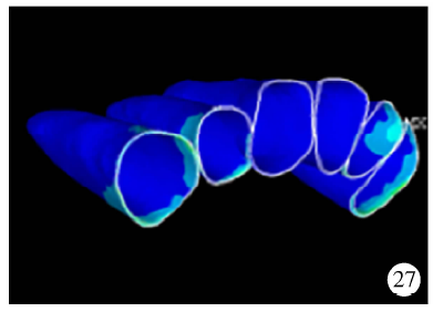 | 图27 颊侧加力1.00 N+腭侧加力0.50 N关闭拔牙间隙时牙周膜von Mises应力分布图Figure 27 The von Mises stress distribution when applied 1.00 N buccal force +0.50 N palatal force in space closure stage |
 | 图28 颊侧加力0.75 N+腭侧加力0.75 N关闭拔牙间隙时牙周膜von Mises应力分布图Figure 28 The von Mises stress distribution when applied 0.75 N buccal force +0.75 N palatal force in space closure stage |
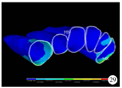 | 图29 颊侧加力0.50 N+腭侧加力1.00 N关闭拔牙间隙时牙周膜von Mises应力分布图Figure 29 The von Mises stress distribution when applied 0.50 N buccal force +1.00 N palatal force in space closure stage |
以往的研究中发现[11], 舌侧矫治单纯腭侧加力关闭拔牙间隙过程中, 容易出现“ 拱形效应” 。对于上前牙, 在矢状方向上可能出现尖牙的近中扭转, 在垂直方向上可能出现中切牙及侧切牙伸长以及尖牙向远中倾斜。随着加力力值的增大, 这些不利的牙齿移动趋势更加明显。与唇侧矫治相比, 这些不利的牙齿移动, 是因为在舌侧矫治中, 牙齿受力点较唇侧矫治更接近牙齿的抗力中心而产生的。以往研究表明[11], 适当地改变加力方式, 调整颊、腭侧加力力值的比例, 可以从一定程度上避免这些不利牙齿移动的发生, 但是调整加力方式和颊、腭侧加力力值比例能否对舌侧矫治中牙周膜的应力分布产生有利的影响, 尚缺乏研究。
牙周膜将牙与牙槽骨相连, 牙周膜是正畸过程中直接的力传导介质[17]。正畸矫治力通过牙齿作用于牙周支持组织, 牙周膜应力大小及分布改变, 引起一系列的生物学反应, 牙周膜中细胞成分改变牙周组织改建[18, 19], 从而导致牙齿的移动[20]。所以牙周组织应力的大小和分布对牙齿的移动具有决定作用。牙根吸收与正畸加力有关[21, 22, 23, 24], Nikolai[25]提出评价最佳力应考虑牙周膜的应力状况, 因其才是推动骨重建和正畸牙移动的关键。综上, 分析牙周膜应力分布具有重要意义。
以往有研究发现[26], 滑动法关闭拔牙间隙过程中, 使用1.50 N力关闭间隙时, 牙齿所受力值在生理范围之内, 并且滑动阻力最小。因此本研究采用1.50 N作为内收前牙的最大力值, 分别在颊侧、腭侧施加0.50 N、0.75 N和 1.50 N 内收力, 以及颊、腭侧加力和1.50 N时不同加力分配比例, 使用三维有限元方法研究舌侧矫治牙周膜应力分布情况。
本研究中发现单纯颊侧加力时, 牙周膜应力集中区主要在尖牙和侧切牙, 因而治疗初期最先可能发生移动的是尖牙和侧切牙, 当力值增大过程中侧切牙牙周膜应力出现明显的增大。
本研究中发现单纯腭侧加力时, 牙周膜应力集中区主要集中在尖牙, 随力值增大尖牙牙周膜应力集中区域扩大同时应力增大, 并未因力值增大而使牙列中其他牙齿出现应力集中区。
从牙周膜应力分布情况上看, 无论单纯颊侧加力还是单纯腭侧加力都有较为明显的牙周膜应力集中区域, 因此颊、腭侧同时加力能有效地分散牙周组织应力集中。
以往研究[11]已经发现了单纯颊侧或腭侧加力, 都会出现牙齿不利的移动趋势。同时, 在本研究中发现, 单纯颊侧加力, 会出现侧切牙及尖牙牙周膜的应力集中, 可能不利于牙齿的生理学移动, 应该在临床中予以关注; 单纯腭侧加力会出现尖牙牙周膜的应力集中, 并随加力力值的增大而增大, 因此当使用腭侧加力时不宜用过大力, 以防止对于尖牙牙周膜的应力集中。在总力值为1.50 N时应用颊、腭侧同时加力, 可以分散牙周应力, 特别是颊侧力值不小于腭侧力值时, 不仅可以避免不利的切牙及尖牙扭转, 同时可以使牙周组织应力分布更为均匀, 避免产生应力集中, 也就减少了上前牙牙槽骨吸收、牙根吸收的可能, 因此推荐在临床中使用总力值1.50 N作为内收前牙关闭拔牙间隙的矫治力, 采取颊、腭侧同时加力, 并且颊侧力值不小于腭侧力值的加力方式, 在个体化舌侧矫治过程中内收前牙关闭拔牙间隙。
The authors have declared that no competing interests exist.
| [1] |
|
| [2] |
|
| [3] |
|
| [4] |
|
| [5] |
|
| [6] |
|
| [7] |
|
| [8] |
|
| [9] |
|
| [10] |
|
| [11] |
|
| [12] |
|
| [13] |
|
| [14] |
|
| [15] |
|
| [16] |
|
| [17] |
|
| [18] |
|
| [19] |
|
| [20] |
|
| [21] |
|
| [22] |
|
| [23] |
|
| [24] |
|
| [25] |
|
| [26] |
|