
探索成人正畸前后下颌三维数字化模型的重叠方法
[戴帆帆1 , 刘怡2 , 许天民2 , 陈贵2, △  ]
]
]
|
|


牙齿移动的测量是评估正畸疗效和生长变化的重要内容之一[1, 2], 也是研究牙齿移动与面部软组织变化之间关系的前提[3, 4, 5]。传统的测量牙齿移动的方法是利用二维的头颅侧位片以及相应的头影重叠法, 常用的头影重叠法包括结构重叠法(structural superimposition)、最适重叠法(best-fit superimposition)和ABO重叠法(American Board of Orthodontics superimposition)[6, 7]。基于上颌骨的重叠可以测量上颌牙齿的移动量, 基于下颌骨的重叠可以测量下颌牙齿的移动量。
不过, 利用二维的头颅侧位片, 牙齿移动的评估仅限于矢状面上垂直向和前后向的平移、磨牙的轴倾和切牙的转矩, 而且由于头颅侧位片上双侧解剖结构的重叠, 无法准确测量出单侧牙齿移动量的变化。
如今, 传统石膏牙颌模型可以通过三维激光扫描仪简单快速地扫描成三维数字化牙颌模型。通过上颌植入正畸种植钉的样本研究发现, 对于成人拔牙病例, 在上颌牙颌模型的腭穹隆部存在一个相对稳定的区域[8, 9], 基于该稳定区域的重叠, 就可以评估上颌每颗牙齿的三维移动。利用数字化牙颌模型重叠的方法来测量牙齿移动的最大优势是无X线辐射。另外, 随着口内扫描设备的发展, 数字化牙颌模型的获取也越来越简便快速, 因此, 利用数字化牙颌模型, 正畸医师们就可以非常方便地在正畸过程中监测上颌牙齿的移动情况。
然而, 对于下颌数字化牙颌模型, 我们至今尚未发现可用于重叠的特征结构或被证实的稳定区域(除外具有明显下颌隆突的情况)[10]。在没有X线片的帮助下, 下颌数字化牙颌模型的准确重叠仍然是一项难题。Park等[11]的研究提出了通过锥形束计算机断层扫描(cone beam computed tomography, CBCT)图像和数字化牙颌模型的配准, 并借助治疗前后CBCT重叠而间接获得下颌牙颌模型重叠的方法, 其他研究也提出直接利用下颌骨的CBCT重叠来测量下颌牙齿的三维移动[12, 13]。但是, 国内大多数医疗机构中CBCT在临床上仍不属于常规检查项目, 而且既往正畸积累的大量资料中也没有CBCT, 那么如何在没有CBCT的条件下实现数字化牙颌模型的重叠来测量下颌牙齿的三维移动仍是个需要解决的问题。
因此, 本研究旨在探索基于头颅侧位片校正间接实现成人下颌数字化牙颌模型重叠的新方法。在下颌牙颌模型重叠后, 对下颌中切牙、尖牙和第一磨牙的三维移动进行测量, 同时, 以基于CBCT图像的下颌模型重叠方法为参照, 通过比较牙齿三维移动量, 对该下颌数字化牙颌模型重叠方法的准确性进行验证。
研究纳入2009年8月至2014年4月于北京大学口腔医院正畸科开始正畸治疗的成人患者共15例, 其中男性5例、女性10例, 年龄范围19~38岁。正畸治疗由两名医师完成, 采用了直丝弓技术矫治, 疗程为18~49个月。
纳入标准:(1)成年患者, (2)牙列完整, (3)咬合稳定, (4)因前突和/或拥挤而拔除了4颗第一前磨牙, (5)治疗前后拍摄了颅面大视野CBCT, 留取了石膏牙颌模型。排除标准:双侧牙颌明显不对称畸形。本研究已通过北京大学生物医学伦理委员会审查批准(审批号:IRB00001052-09010), 并获取了患者知情同意。
患者治疗前后的CBCT由同一技师用同一设备(DCT Pro, Vatech Co., Yongin-Si, Korea)拍摄, 拍摄参数为:拍摄视野20 cm× 19 cm, 管电压90 kV, 管电流7 mA, 拍摄时间15 s, 层距0.5 mm。拍摄时要求患者取自然头位, 下颌处于牙尖交错位。石膏牙颌模型经三维激光扫描仪(3Shape R700, 3ShapeA/S, Copenhagen, Denmark)扫描转化为数字化牙颌模型, 扫描精度为± 0.02 mm。
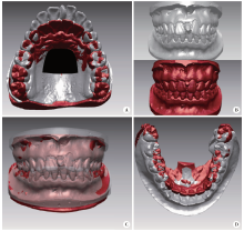
利用逆向工程软件Rapidform 2006(Inus Technology, Seoul, Korea)首先将治疗前后上颌牙颌模型于腭部稳定区域采用迭代最近点方法进行配准(图1A)[8]。治疗前后的下颌牙颌模型根据上下颌之间的咬合关系分别与治疗前后的上颌牙颌模型进行咬合定位, 从而获得治疗前后下颌牙颌模型初始配准的结果(图1B~D)。
 | 图1 基于上颌模型的初始下颌牙颌模型重叠Figure 1 Maxilla-based initial registration of mandibular dental casts A, superimposition of pre- (gray) and post-treatment (red) maxillary dental casts registered on the palatal stable region (black); B, maxillary and mandibular dental casts in maximum intercuspal occlusion; C, pre- and post-treatment mandibular dental casts were transferred to the already superimposed maxillary casts using the occlusal relationship; D, the initially superimposed pre- and post-treatment mandibular dental casts. |
利用Dolphin影像软件(Version 11.7, Dolphin Imaging & Management Systems, Chatsworth, Calif)将CBCT图像以正交投照(模拟X线平行投照, 无放大率)方式生成头颅侧位片[14, 15]。对治疗前后头颅侧位片进行描记, 并于前颅底结构(包括蝶鞍前壁、颅中窝和筛板, 因样本为成人, 可同时参照其他颅上颌骨结构)进行重叠, 测量出下颌骨治疗前后相对于前颅底的转动和平移量。
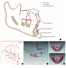
具体操作如下:以平均功能牙合平面(functional occlusal plane, FOP)为X轴, X轴的垂线为Y轴建立坐标系, 在治疗后头颅侧位片上定位髁顶点(Co), 测量正畸治疗后下颌骨绕Co点的旋转量(MCoR)及下颌骨沿X轴和Y轴的平移量(MT_X和MT_Y), 即当治疗后下颌骨绕Co点旋转MCoR后, 其与治疗前下颌骨处于平行状态, 接着沿X轴和Y轴分别平移MT_X和MT_Y后, 其与治疗前下颌骨重合(图2A)。另外, 在治疗后头颅侧位片上记录下第二磨牙最远中点(LM2)至Co点的距离(MCoD)及下中切牙切缘点(LI1)至Co点的距离ICoD(图2B)。
 | 图2 下颌旋转量和平移量的测量和校正Figure 2 Measurement and adjustment of mandibular rotation and translation A, the post-treatment mandible (red) rotated around the condyle point (Co) until it (green) was parallel to the pre-treatment mandible (black), with the degree of rotation being recorded as MCoR; the green mandible was then translated sagittally and vertically until it coincided with the pre-treatment mandible, with the amounts of translation being recorded as MT_X and MT_Y respectively; B, measurements on the post-treatment cephalogram; C, within the Rapidform software, the Co was located according to the measurements in the cephalorgram, adjustment was done with the initially superimposed post-treatment digital cast rotated around the Co by MCoR and translated by MT_X and MT_Y; D, presentation of the pre- and post-adjustment mandibular digital cast superimposition results. FOP, functional occlusal plane. |
将1.3小节中头颅侧位片前颅底重叠获得的下颌变化量转移到1.2小节完成的数字化下颌模型初始重叠上, 从而实现下颌数字化模型的最终重叠。
具体操作如下:(1)建立平面及三维坐标系。在Rapidform软件中, 对于初始配准后的下颌牙颌模型, 建立平均FOP和正中矢状平面。平均FOP为治疗前后上下颌第一磨牙、第二前磨牙及第一前磨牙的颊尖点和舌尖点拟合而成; 正中矢状平面为过腭中缝且垂直于FOP的平面。在正中矢状面上根据头颅侧位片中的定义建立X轴和Y轴, 即以FOP与正中矢状面的交线为X轴, X轴的垂线为Y轴, 两者的垂线为Z轴, 从而建立三维坐标系。(2)下颌旋转量和平移量的校正。将治疗后下颌模型双侧牙列投影至正中矢状面上, 获得下牙列轮廓线。参照头颅侧位片中的定义定位LM2点和LI1点, 并根据MCoD和ICoD的距离定位Co点, 然后根据头颅侧位片重叠测得的MCoR、MT_X和MT_Y值对治疗后下颌牙颌模型进行沿Co点的旋转和沿X轴、Y轴的平移(图2C), 从而完成校正并获得下颌模型重叠的最终结果(图2D), 此时治疗前后下颌牙齿移动的评估是基于下颌骨重叠的状态下。
将治疗前后的CBCT图像导入Mimics软件(version 10.01, Materialise, Leuven, Belgium)中, 对下颌骨和下牙列进行分割和三维重建并以STL格式输出, 在Rapidform软件中将治疗前后的下颌骨模型以下颌骨升支和位于牙根下方5 mm以下的体部进行区域重叠(图3A), 再将治疗前后的数字化牙颌模型经牙冠区域配准替代CBCT来源的下牙列(图3B~D), 从而获得基于CBCT的下颌数字化牙颌模型重叠结果(图3E)。
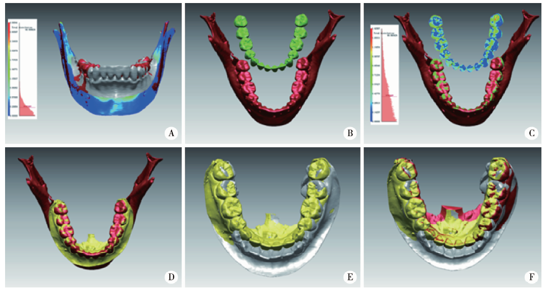 | 图3 基于CBCT的下颌牙颌模型重叠Figure 3 CBCT-based registration of mandibular dental casts A, registration of mandibular models (gray, pre-treatment; red, post-treatment), the average distance deviation being less than 0.3 mm; B-C, the dental arch from the digital dental cast (green) was superimposed onto the mandibular model by dental crown surface superimposition, the average distance deviation being less than 0.4 mm; D, the location of the dental arch was replaced by the whole dental cast (yellow); E, the superimposition result of mandibular models was transformed to superimposition of dental casts (gray, pre-treatment; yellow, post-treatment) after the pre- and post-treatment dental casts were superimposed onto the pre- and post-treatment mandibular models respectively; F, integration of the superimposition results from the lateral cephalogram-based mandibular digital cast superimposition (gray and red) and the CBCT-based mandibular digital cast superimposition (gray and yellow). |
研究以基于CBCT的下颌牙颌模型重叠为参照, 验证基于头颅侧位片的下颌牙颌模型重叠方法的准确性。在Rapidform软件中的共同坐标系下, 于治疗前牙颌模型上选定两侧下第一磨牙的近中颊尖(LM和RM)、下尖牙的牙尖(LC和RC)和下中切牙切缘中点(LI和RI), 并通过牙冠配准方法将相同标志点转移至治疗后牙颌模型上, 避免重复定点误差。测量治疗前后各标志点三维坐标的变化以分别代表下第一磨牙、尖牙和中切牙的三维位移, 对两种重叠方法下三维牙齿移动量进行比较。
利用PASS软件(Version 11.0; NCSS, Kaysville, UT, USA)进行样本量计算, 对于采用配对t检验比较基于头颅侧位片和基于CBCT的两种下颌牙颌模型重叠方法下牙齿三维位移的差异, 根据临床意义水平设定两组差值为0.5 mm, 根据研究初期测量结果设定方差为0.5 mm, 在P< 0.05(双侧)、把握度80%的情况下, 研究所需最低样本量为11例。统计分析在SPSS软件(Version 19.0; IBM, Armonk, NY, USA)中进行。下颌模型的重叠和测量由同一名研究者重复操作两次, 利用组内相关系数(intraclass correlation coefficient, ICC)评价操作者自身的可靠性, 结果ICC值均大于0.97。经Kolmogorov-Smirnov检验, 所有数据均符合正态分布, 采用配对t检验比较两种配准方法下颌牙齿移动量的差异, P< 0.05为差异有统计学意义。
表1显示了治疗前后头颅侧位片基于前颅底重叠时测得的下颌骨的旋转量和平移量, 即对于初始重叠的下颌数字化牙颌模型, 所需校正的下颌旋转量为-2.0° ~0° , 所需校正的下颌平移量在前后方向上为-1.6~1.3 mm, 垂直方向上为0~1.4 mm。
| 表1 基于头颅侧位片重叠测量得到的所需校正的下颌骨的旋转量和平移量 Table 1 Adjustment amounts of mandibular rotation and translation measured from lateral cephalometric superimposition |
表2显示了两种重叠方法时下颌第一磨牙、尖牙和中切牙的三维位移。正畸治疗后, 双侧第一磨牙平均前移了2.0 mm, 伸长了1.3 mm, 磨牙间宽度缩窄了2.1 mm; 双侧尖牙平均内收了5.4 mm, 伸长了0.2 mm, 尖牙间宽度增加了0.8 mm; 双侧中切牙平均内收了4.4 mm, 压低了0.8 mm, 切牙间宽度增加了0.4 mm。
| 表2 基于头颅侧位片的下颌牙颌模型重叠与基于CBCT的下颌牙颌模型重叠所测下颌牙齿三维位移量 Table 2 Mandibular tooth movement measured from the lateral cephalogram-based mandibular digital cast superimposition and CBCT-based mandibular digital cast superimposition |
表3显示通过配对t检验比较, 第一磨牙的三维位移、尖牙和中切牙的矢状向和垂直向位移在两组间差异无统计学意义, 但尖牙和中切牙的水平位移在两组间差异有统计学意义, 差值为(0.3± 0.5) mm。
| 表3 基于头颅侧位片的下颌牙颌模型重叠方法与基于CBCT的下颌牙颌模型重叠方法下颌牙齿三维位移量的比较 Table 3 Differences of tooth movement between the lateral cephalogram-based mandibular digital cast superimposition method and the CBCT-based mandibular digital cast superimposition method |
在成人拔牙正畸的种植钉样本研究中已发现, 上颌牙颌模型存在一腭部稳定区域可用于上颌牙颌模型的配准[8]。然而, 在下颌牙颌模型中, 以往研究尚未找到可供配准的特征结构或相对稳定的区域(除外具有明显下颌隆突的情况)[10]。因此, 本研究探索了间接实现下颌牙颌模型重叠的新方法, 在此方法中, 上颌牙颌模型的重叠、咬合转移、利用头颅侧位片进行下颌旋转量和平移量的校正这三个步骤依次进行, 前两步得到的是基于上颌骨重叠的下牙列变化, 而在第三步操作后才最终获得基于下颌骨重叠的下牙列变化。
本研究探索的基于头颅侧位片的下颌牙颌模型重叠方法适用于没有CBCT而只有牙颌模型和传统头颅侧位片的情况。不过, 为了采用基于CBCT的下颌牙颌模型重叠法[11]为参照来验证此方法的准确性, 本研究仍选择了治疗前后拍摄了CBCT的样本, 而头颅侧位片是由CBCT图像经正交投照生成的, 以避免再次投照传统头颅侧位片所带来的过多X线放射。既往研究表明, CBCT合成的头颅侧位片无论是以正交投照方式还是以透视投照方式生成, 与传统头颅侧位片相比, 大多数头影测量项目的测量值均无明显差异[14, 15]。
正畸治疗后下颌骨相对于上颌骨的位移变化可分解为下颌骨绕Co点的旋转量和下颌骨沿FOP或垂直于FOP的平移量。尽管Co点并非准确的髁突旋转中心[16, 17], 但从数学上来分析, 任何刚性物体从一个位置到另一个位置的位移变化均可以分解为绕任意一点的旋转量及在相应坐标系下的平移量[18]。因此, 只要头颅侧位片中的Co点和FOP平面在数字化牙颌模型的坐标系中得到复制, 头影重叠测量得到的下颌骨的旋转量和平移量就可以用于校正下颌牙颌模型的重叠。
本研究以基于CBCT的下颌牙颌模型重叠为参照来评估基于头颅侧位片的下颌牙颌模型重叠的准确性。治疗前后CBCT来源的下颌骨模型配准的平均误差小于0.3 mm(图3A), 提示配准结果准确。由于直接在CBCT图像上进行牙齿测量不如在数字化牙颌模型上测量准确[19], 研究中我们通过牙冠表面区域配准将数字化牙颌模型与CBCT来源的下颌骨模型进行整合。有研究报道, 两者整合时若利用牙冠的颊舌面进行配准, 误差为0.3 mm[20], 本研究中利用了整个牙冠的表面进行配准, 误差在0.3~0.5 mm(图3C), 与之接近。另外, 在测量比较两种重叠方法下牙齿的位移量时, 为了减小定点误差, 本研究通过牙冠配准, 将治疗前牙颌模型上选定的标志点转移至治疗后牙颌模型上, 牙冠配准的误差小于0.1 mm。
本研究结果显示, 基于头颅侧位片的牙颌模型重叠与基于CBCT的牙颌模型重叠方法评估下颌牙齿移动时在X轴与Y轴方向上具有相同的准确性, 但在Z轴方向即水平方向上, 两者前牙移动量的差异为(0.3± 0.5) mm (P< 0.05), 这可能与利用头颅侧位片进行校正的局限性有关。正畸治疗后下颌骨的位置变化是三维的, 而利用头颅侧位片仅能校正下颌骨在矢状平面上的位移, 不能校正其在冠状面和水平面的位移, 因此将导致下颌牙颌模型重叠在Z轴方向上的误差。不过, 在Z轴方向上的平均误差不超过0.3 mm, 处于临床可接受水平。研究结果也间接提示正畸治疗后下颌骨在冠状面和水平面的位移变化是很小的。
利用治疗前后CBCT图像, 通过重建的下颌骨表面模型重叠[11]或通过下颌骨体数据的体素重叠[12, 13, 21], 可以直接、便利地评估下颌牙齿的三维移动。然而, 本研究提出的基于头颅侧位片的下颌牙颌模型重叠方法, 仅利用临床常规资料, 即牙颌模型和头颅侧位片, 来实现下颌牙齿三维移动的评估, 因此更广泛适用于临床应用, 尤其是可应用于既往没有CBCT条件下留取的历史正畸临床资料。操作上特别需要注意的是, 利用该重叠方法时需要检查头颅侧位片中的咬合是否与牙颌模型的咬合一致, 否则将影响下颌骨旋转和平移量的校正, 另外, 在采用传统头颅侧位片校正时, 对下颌骨的平移量需进行放大率校正。
本研究提出的下颌模型重叠方法的不足之处在于重叠步骤相对复杂, 每一步都需要仔细操作, 同时需要熟练掌握Rapidform三维软件的应用, 整个重叠过程用时较长。
综上所述, 基于头颅侧位片的下颌牙颌模型重叠方法与基于CBCT的下颌牙颌模型重叠方法在评估下颌牙齿三维移动时具有相似的准确性, 两者仅在下前牙水平方向的位移上具有少量差异。
The authors have declared that no competing interests exist.
| [1] |
|
| [2] |
|
| [3] |
|
| [4] |
|
| [5] |
|
| [6] |
|
| [7] |
|
| [8] |
|
| [9] |
|
| [10] |
|
| [11] |
|
| [12] |
|
| [13] |
|
| [14] |
|
| [15] |
|
| [16] |
|
| [17] |
|
| [18] |
|
| [19] |
|
| [20] |
|
| [21] |
|